Advanced Settings
The advanced settings, contains three tabs:
- Design Tab which holds
information about the design matrix. Here the hemodynamic
response function (HRF) can be modified as well.
- Preprocessing Tab
where preprocessing steps can be modified, and/or turned on/off.
- GLM Settings Tab
where settings used in the GLM
estimation can be modified.
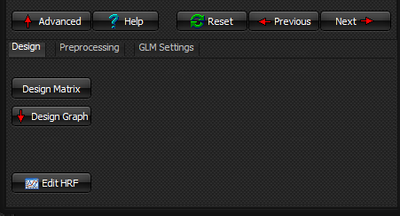
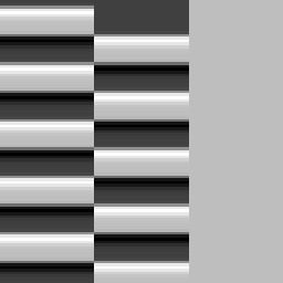
Design Tab
Design
Matrix button
Displays the design
matrix.
The design matrix models the input paradigm, where the stimulus is convolved
with a HRF. It is used in the GLM estimation.
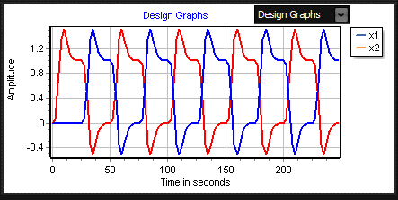
Design Graph button
Design Graphs
Displays the design matrix graphically.
Boxcar
Graphs
Displays the input paradigm as a boxcar graph.
Edit HRF button
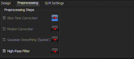
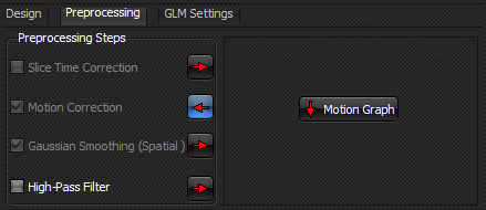
Preprocessing Tab
Slice Time Correction
Check to perform slice time correction. Please note that it is the user’s responsibility to set up the slice time acquisition mode.
Slice time correction is done to correct for the fact that for a
given volume in the image time-series, each slice is acquired at a different
time point. The correction is done using spline interpolation.
For blocked designs, slice time correction might not be critical
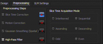
Specifying Slice Time Acquisition Mode
Specifying the slice time acquisition mode is the same as setting
up the order of the acquisition. The different possibilities are:
·
Interleaved
ascending (odd start scan)
·
Interleaved
descending (odd start scan)
·
Interleaved
ascending (even start scan)
·
Interleaved
descending (even start scan)
·
Sequential
ascending
·
Sequential
descending
Note that the slices are
numbered from 1. Therefore, if there are 10 slices in a
volume, an ascending interleaved sequence with odd start scan would be
{1-3-5-7-9-2-4-6-8-10}.
Motion Correction
Check to perform
motion correction.
Motion correction is done to correct for subject movement in the scanner, by
estimating the rotation and translation of the volumes in the image
time series to a reference volume. Then the volumes are shifted
according to the estimated rotation and translation, using a cubic shift
operation.
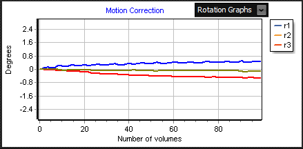
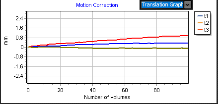
Motion Graph button
Display the estimated rotation and translation parameters
graphically. Choose which parameters to display from the drop down menu as illustrated
below. The button is enabled after motion correction has been performed.
Rotation
Graphs
Display estimated rotation parameters graphically.
Translation
Graphs
Displays estimated translation parameters
graphically.
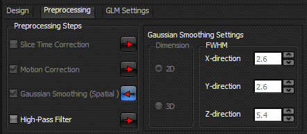
Gaussian Smoothing (Spatial)
Check to perform
Gaussian spatial smoothing.
Gaussian spatial smoothing is performed to blur and reduce high-frequency
spatial noise in the images. The user can alter the dimensionality of
the filter, applying either a two-dimensional (within slice) or a
three-dimensional (within volume) filter. The full-width-half-maximum
(FWHM) in millimetres of the filter can also be altered. By default,
the FWHM is about twice the voxel size in all directions.
High-Pass
Filter
Check to perform
temporal high-pass filtering.
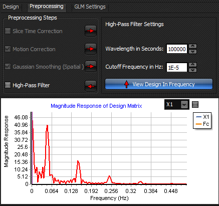
A temporal high-pass filter is applied to reduce low frequency drifts in the
image time series. In this application a Butterworth filter is
applied. The user can choose to either specify the filter's wavelength in seconds or the cutoff frequency in Hz. Specifying a
wavelength of e.g. 120 seconds as below, results in a cutoff frequency of
1/120 Hz. This means that frequencies below the cutoff frequency are filtered
out of the image time series. Therefore, it can be dangerous to apply this filter if the right wavelength/cutoff frequency
is not specified. The frequencies that are filtered out are illustrated
graphically by pressing the view design
in frequency button.
Please note that
using a wavelength in seconds that is too short for the given problem, you
might end up filtering out the BOLD response. It is the user's responsibility
to set up the correct wavelength.
Wavelength in Seconds
Specify the wavelength of the high-pass filter in seconds. The cutoff frequency in Hz
is automatically updated.
Cutoff Frequency in Hz
Specify the cutoff frequency of the high-pass filter in Hz. The wavelength in seconds is automatically
updated.
View Design In Frequency Button
Press to view the
design matrix graphically in the frequency domain. The vertical line
illustrates the cutoff frequency.
Note that frequencies from 0 to the vertical line
are filtered out.
Drop Down Menu
Use drop-down menu to
alternate between different regressors in the design matrix.
Check to display all the regressors in design matrix.
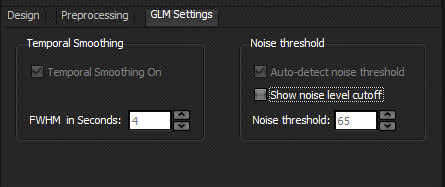
GLM Settings Tab
Holds settings related to the GLM
estimation which can be changed by the user.
Temporal Smoothing
Temporal smoothing using a Gaussian filter is performed for
the GLM estimation. It will
influence the degrees of freedom used in the statistical analysis.
Temporal
Smoothing On
Check to turn on temporal smoothing. By default, temporal
smoothing filter is on. It is applied both to the image data and the design
matrix.
FWHM
in Seconds
Set the FWHM of the temporal smoothing filter. The default value
is 4 seconds.
Threshold Data
Thresholding of the image data is done only for the GLM estimation, so that the image voxel
information in the time series will not be affected by the threshold. A
default threshold value is estimated automatically when the BOLD module is
opened, as the mean intensity of the first volume, divided by 4.
The voxels with intensity below the threshold is marked in red. In
the GLM estimation, the first volume is used
as a reference point where values below the given threshold for this volume,
will be omitted in the estimation. The output of the GLM estimation corresponding to these voxels will
therefore be zero.
Threshold
On
Check to turn on voxel threshold. The default is on.
Display
Voxel Threshold
Check to display voxels which are not included in the GLM estimation. The excluded voxels are displayed in
red. The default is on.
Threshold
Value
Displays voxel threshold value.
Related
topics:
Edit
existing or creating new design file
Create paradigm in design file
Specify contrasts in design file
Specifying processing steps in design file
Edit hemodynamic response function (HRF)
General linear model (GLM) estimation

|