Signal (SI)
conversion
Specifies how the
signal time curves in the input images should be converted prior to analysis:
- SI to delSI: the SI is converted to SI difference from baseline:
delSI(t) = S(t)-So.
This conversion is typically used for CT images and T1-weighted MR
images.
- SI to relSI (%): the SI is converted to percent change in SI using
the expression: relSI(t) =
100*(S(t)-So)/So
- SI to delR2:
the SI is converted to relative change in R2 (i.e
R2* = 1/T2*) using the standard expression: delR2(t) = -ln(S(t)/So)/TE
where S is the SI at time t, So is the baseline
SI and TE is the echo time. Note that this type of signal conversion is
rarely used in DCE image analysis.
- 1/T1 from SPGR: converts
to change in 1/T1 relaxation rate for spoiled gradient echo (GRE)
sequence. See Theory section for
details. Flip angle and repetition time (TR) must be specified in
the <Parameters> field or be available from the image header (for Dicom images).
- 1/T1 from SR images:
converts to change in 1/T1 relaxation rate for saturation recovery (SR)
sequence. See Theory section for
details. Delay time (TD)must be specified in the
<Parameters> field.
- None:
the input signal is not modified. Note that this setting assumes the
input images have already been converted to either relative SI change or
delR2 change.
Note that the first-pass curve should always have a 'positive' peak . If the first-pass curve has a negative peak or
a non-zero baseline value you need to convert it
using the appropriate SI conversion function.
Setting Baseline T1
For SPGR and SR conversion (see above) the baseline (pre-contrast)
T1 value must be known for each voxel. This can either be set to a fixed
value (T1=1000 ms by default) or extracted
voxel-wise from a T1-map supplied separately:
- Set T1 value: The
T1-value is fixed at the specified value for all voxels
- Drag T1 image: If
selected, a small window becomes visible (see figure below). A
separately generated series of T1-maps can then be dragged into this
window which will initiate an automatic coregistration of the T1-maps
with the DCE image series (see image Co-registration).
The T1-values from the T1-maps will then be used as baseline T1-values
in the subsequent calculations. The T1-maps can be generated from
multi-flip or multi-inversion (e.g. Look-Locker
type) acquisitions in the nordicICE T1-relaxation
module.
- Note that the baseline T1-options should be set prior
to AIF determination for correct scaling of the AIF.
- Specification of baseline T1 is only used when SI
conversion is set to either SR or SPGR (see Theory
for details)
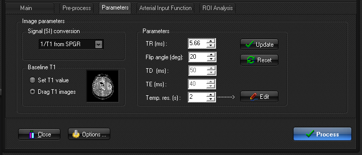
Figure 1.
Inclusion of T1-map for correct conversion of SI to CA concentration. The
T1-map (generated separately) can be dragged into the small image
window once this option is selected. The T1-map will be used for all
subsequent analysis of concentration time curves using
the appropriate signal conversion according to the imaging
sequence selected in the 'SI signal conversion' drop-down menu. See Theory for details.
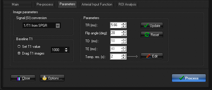
Sequence
Parameters
The parameters which
need to be specified here depend on the type of image conversion selected.
- TR (repetition time in ms):
needed for conversion of SI to 1/T1 for SPGR
sequences
- Flip angle (degrees): needed for conversion of
SI to 1/T1 for SPGR sequences
- TD (delay time in ms):
needed for conversion of SI to 1/T1 for saturation recovery (SR)
sequences
- TE (echo time in ms):
needed for conversion of SI to 1/T2 for T2-weighted or T2*-weighted GRE
or EPI images
- Temporal resolution (in seconds): needed for all
image types.
Note that all image parameters except for temporal resolution
are only applicable to MR images. For DICOM images, many of the
parameters above may be automatically extracted from the image header. If the
displayed value is incorrect it can be edited
manually. If the temporal resolution is incorrect you may want to specify a
different DICOM tag to be used to extract the termporal
information. See <Image Format Options> for
more details, and remember to click 'Update' if
changes are made. If the parameters cannot be determined (non-DICOM images) a
warning message is issued and the values must be set
manually. Note that the TE value is only needed if the data is to be
converted from SI to delR2. Note that the temporal spacing between successive
dynamic images can be non-constant. If the temporal identifiers are not found
in the DICOM header (or not DICOM images) and the spacing is not constant
between successive images, then the actual image times can be specified in a
list accessed from the <Edit> button.