|
|
|
|
Diffusion Tensor
Imaging Analysis
The
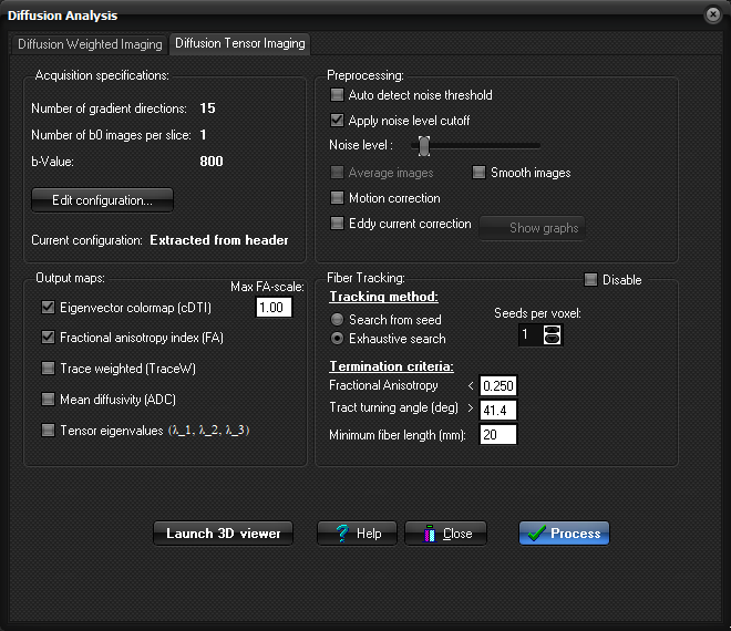
Diffusion Analysis dialog contains the following tabs
Note: The Diffusion
Tensor Imaging tab can be displayed by selecting Diffusion Analysis
(DTI) on the Modules menu. Acquisition
parameters:
Number of gradient directions: Here the number of gradient directions in the
input images is displayed. If this information is not yet defined, the value
will display here. In this case manual definition is required by clicking the
Edit configuration button. Preprocessing:
Auto detect noise
threshold: Toggle on/off auto-detection of noise threshold. Show noise level cutoff: Show the pixels in the input images that are below current Noise
level threshold in red. Motion correction: When selected, motion
correction will be performed prior to diffusion map generation. See Motion and eddy current correction for details on the
algorithms used. Eddy current correction: When selected, eddy current compensation will be performed prior
to diffusion map generation. See Motion and eddy
current correction for details on the algorithms used. Show graphs: Shows the result from the Motion and/or Eddy
current correction (if/when performed). Output
Eigenvector color map (cDTI) : Generates
diffusion tensor colormaps (color DTI) where the
pixel color reflects the direction of the diffusion
tensor in that voxel. The color coding is
implemented by scaling the directions of the eigenvector with the largest
eigenvalue according to the scheme (AXIAL):
The intensity of the colors are scaled
with the Fractional Anisotropy (FA) index. The maximum scaling FA-value to be
applied in this scaling can be modified by the Max FA-scale box.
Default, the intensity in these maps will be scaled with the FA-value from 0
to 1, but the maximum value can be set e.g. to enhance intensity within
regions/images having low FA-values. Note that this factor does not influence
the FA-values themselves (FA-maps), but only the visual representation of the
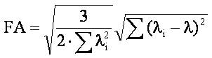
cDTI maps on screen. Fractional Anisotropy
Index (FA) : Generates maps reflecting the
fractional anisotropy of each voxel. The index range is 0-1. The values
are calculated according the following formula:
Trace Weighted (TraceW) : Generates maps reflecting the
geometric average of the individual diffusion weighted images. These
maps are comparable to orthogonal DWI, and has a contrast reversal as
compared to the ADC image. Mean diffusivity (ADC) : Generates
maps reflecting the trace of the diffusion tensor (Tr(D)/3). The mean
diffusivity map is scaled so that the pixels are in units of 10-5 mm2
/s. The values are calculated according to the following formula:
Tensor eigenvalues: Generates
(3) maps reflecting the individual eigenvalues of the diffusion tensor. The
eigenvalues are sorted in descending order, i.e. lambda_1 > lambda_2 >
lambda_3. Fiber Tracking:
Disable: Check this
checkbox if you do not want to perform any fiber tracking (only calculate
maps). Disabling the fiber tracking will save resources (memory). Tracking method: Choose the tracking method approach:
Termination criteria: Set the tracking termination criteria:
Seeds per voxel: Number of randomly distributed seed-points to
be used for every seed-voxel Perform Fiber
Tracking: Select this
option to perform Fiber Tracking immediately after DTI maps has
been generated. This will cause Fiber Tracking to be performed using an
exhaustive search algorithm trying to reconstruct all white matter fiber
tracts in the brain. Process:
Start processing the data Launch 3D viewer: Launch the MPR window with the DTI 3D window and DTI Interaction
Panel. |
|