|
|
DTI
Gradient Configuration
Note:
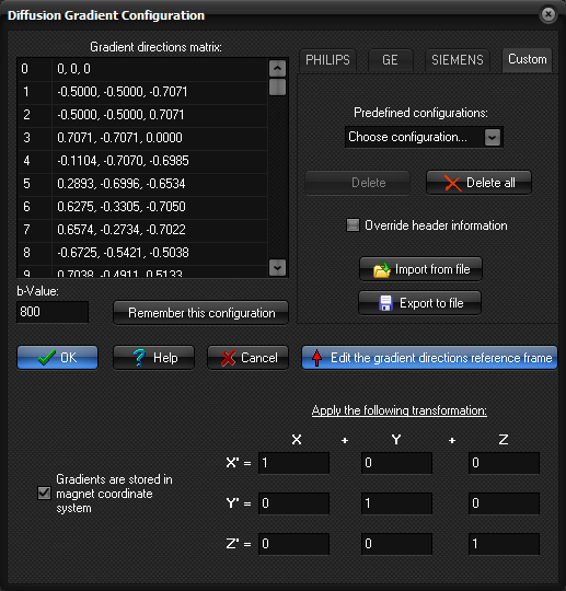
The DTI Gradient Configuration dialog can be displayed by clicking on
the Edit configuration ... button of the Diffusion Tensor Imaging
tab of the Diffusion Analysis dialog box.
This dialog can be used to manually specify the diffusion
gradient directions for a given DTI input dataset in the case where this
information was not available from the DICOM header. There are various
standard configuration setups commonly used by the different MR vendors,
which can be found under 3 individual tabs for respectively PHILIPS, GE
and SIEMENS scanners. In addition, a Custom tab enables the
user to load and manage various customized configurations.
Gradient directions matrix: Table showing the current defined
diffusion gradient directions. Each row corresponds to a image in the dynamic
sorted image stack, i.e. the first row corresponds to the first image in
every slice, the second row to the second image in every slice and so on. By
clicking on a given row, the image window holding the input images will be
updated to show the image which the row corresponds to. By clicking on the
button ("…") at the right of each row a popup menu will appear:

This menu can be used to manual edit the configuration matrix:
Insert 'Excluded
image'...: Inserts a
"EXCLUDED" image entry either at the current selected row ('here')
or at the last row of the table ('last').
Insert 'b=0' image...: Inserts a b=0 image entry either at the current
selected row ('here') or at the last row of the table ('last').
Duplicate table (add repetitions) ...: Duplicate the table in two or
more (up to six) repetitions. This option can be used if the input dataset
holds multiple repetitions of the same DTI sequence.
Delete this entry: Delete the current selected row from the table.
Clear table: Clear (delete all entries) from the table.
b-Value: The b-value used in the diffusion weighted images (only 1 b-value
can be specified).
Remember this configuration: Add the current defined (gradient
directions & reference frame and b-value) configuration to the list of Predefined
configurations. This will save the configuration to a internal
configuration file, allowing the configuration to be applied also in subsequent
sessions. When doing this, you will be prompted to type a description that
will be used to identify the configuration. Whenever the DTI-module is
launched on a dataset, the list of Predefined configurations will be
searched for a match, i.e. if the number of images per slice corresponds to
the number entries in the gradient table, this configuration will be
automatically loaded. The name of the configuration will then be displayed in
the Current configuration field in the Diffusion
Tensor Imaging tab.
Predefined configurations: Drop-down menu holding
the configurations previously defined by the user. When you click the Remember
this configuration button, the current configuration will be saved and
the configuration will be added to this menu.
Delete: Delete the currently selected configuration from the Predefined
configurations menu.
Delete all: Delete all configurations from the Predefined
configurations menu.
Override header information: Let the user defined configurations override
any information that might be extracted from the DICOM header. This is useful
if e.g. the information written by the scanner in the DICOM header is not
correct, and you always want the Predefined configurations to be used
as default.
Import from file: Import/load a configuration from a
text-file. The input file format must consist of one direction vector
per line; i.e
0, 0, 0

0.8944, 0.0000, -0.4473

0.0000, -0.4473, -0.8945

0.4472, -0.8945, 0.0000

...
where (0,0,0)
corresponds to a b=0 image. Specifying the vector (100,100,100) will cause
the corresponding image to be EXCLUDED from the analysis. The number of
entries in the table must match exactly the number of images per slice in the
input dataset, and that the first entry corresponds to the first image, the
second entry to the second image and so on.
Export to file: Export/save the current configuration to a text-file.
Edit gradient directions reference frame: Displays the panel
showing the transformations that will be applied to the gradient directions
prior to the analysis. This can be used to specify the reference frame of
which the gradient directions are defined, as this may vary depending of MR
vendor and the protocols used. For fiber tracking it is important that the
directions are transferred to the image (voxel) coordinate system prior to
the analysis.
Related topics:
Diffusion
Analysis
Diffusion Analysis (Optional plugin module)

|
|